Project overview
This project is a hands-on exploration of computer architecture, starting with the 6502 microprocessor. It covers everything from basic circuits to advanced programming techniques. The goal is to build a fully functional computer that can run simple programs, providing a deep understanding of how computers work at a fundamental level.
1 MHz Clock
Generates a 1 MHz signal used to synchronize the CPU and other components — essential for timing and correct data processing.
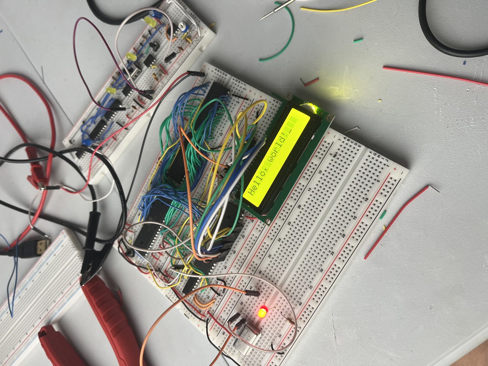
Fully Working Hello-World Program
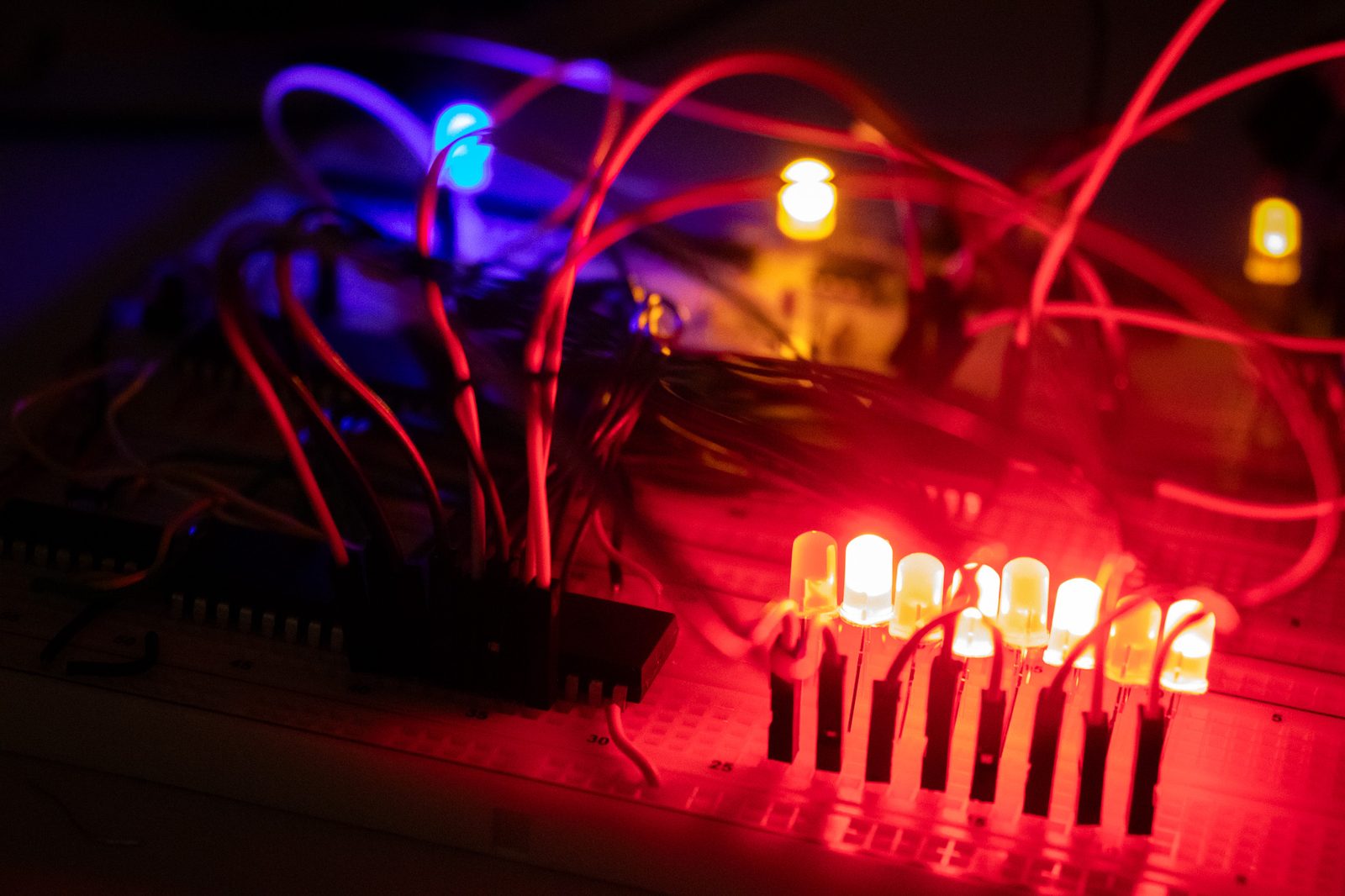
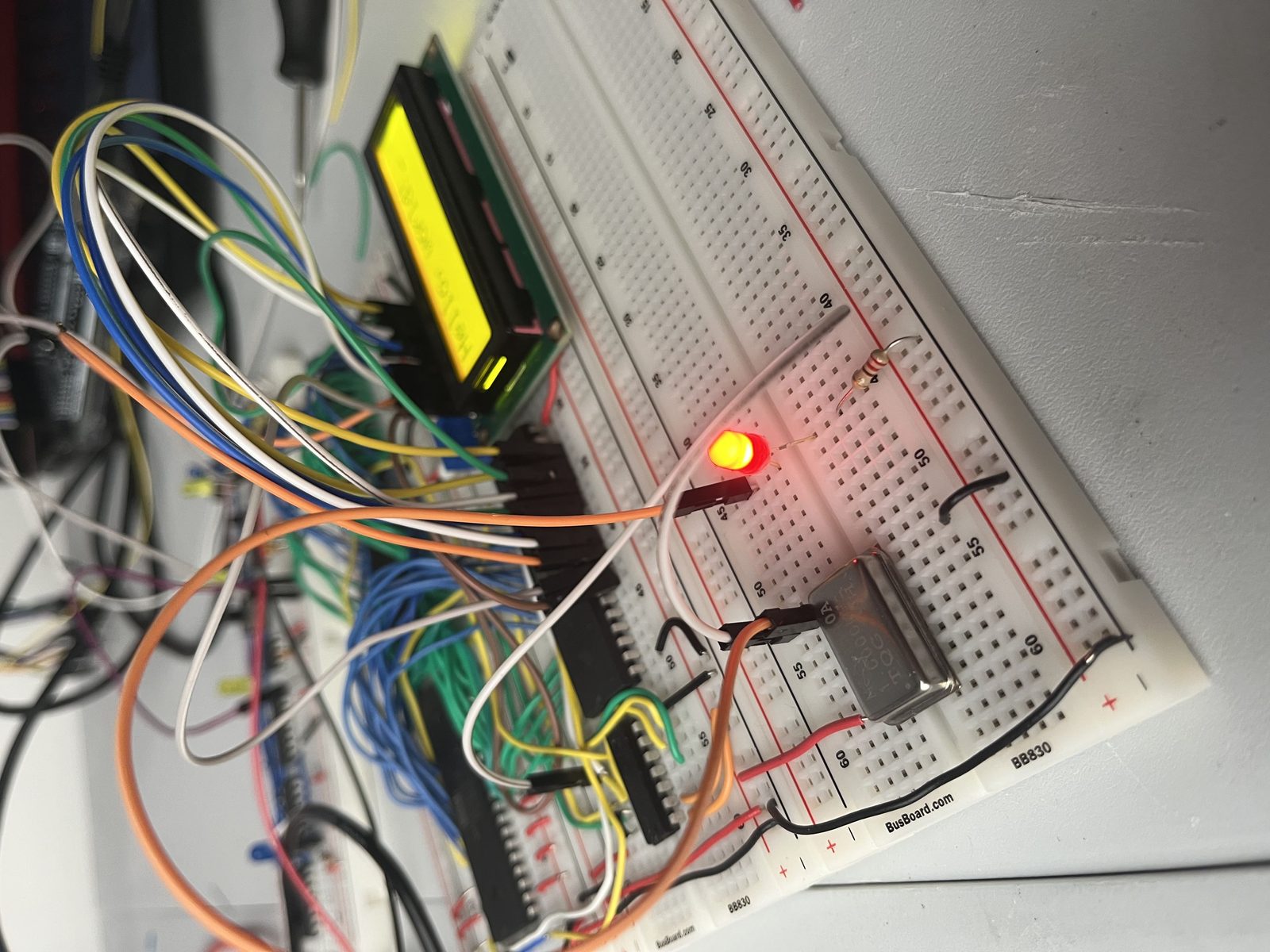
Flipping LEDs from hex 55 to AA
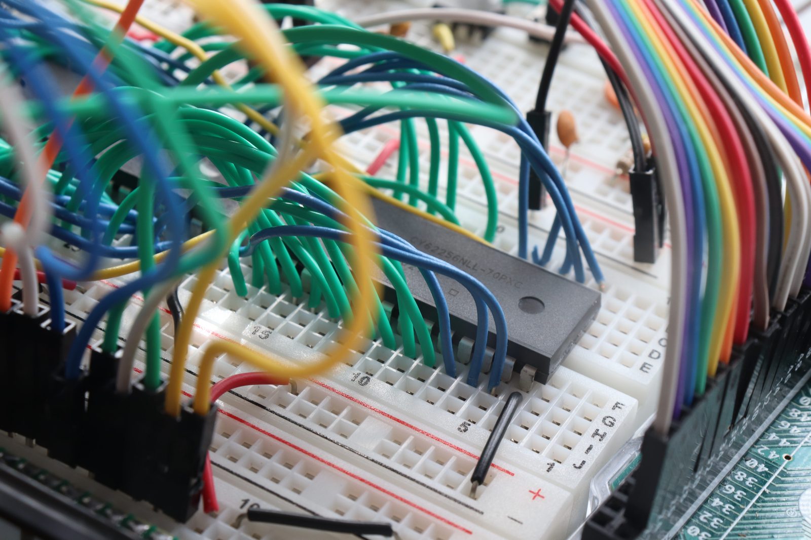
The ROM Chip
Contains the firmware and is essential for booting — stores the program the CPU executes on power-up.
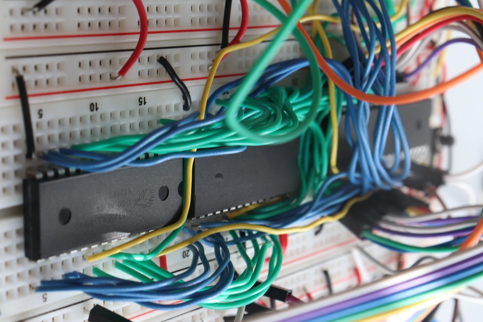
The ROM and RAM Chips
ROM stores program instructions; RAM holds temporary data during execution.
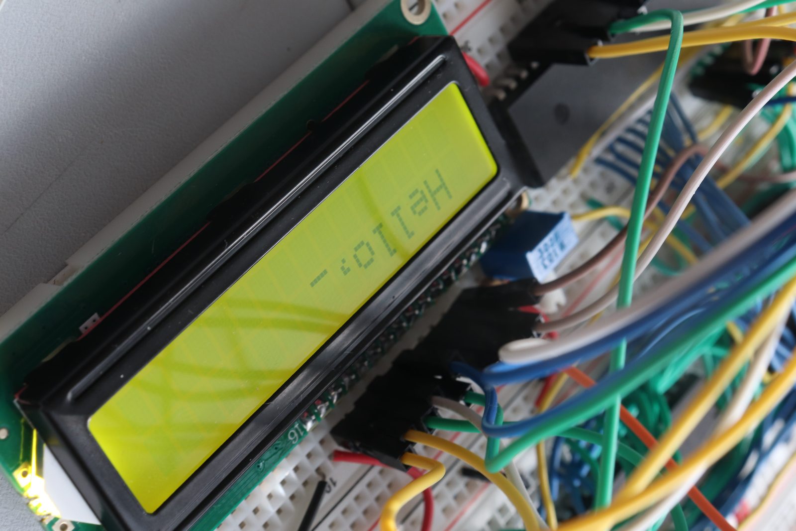
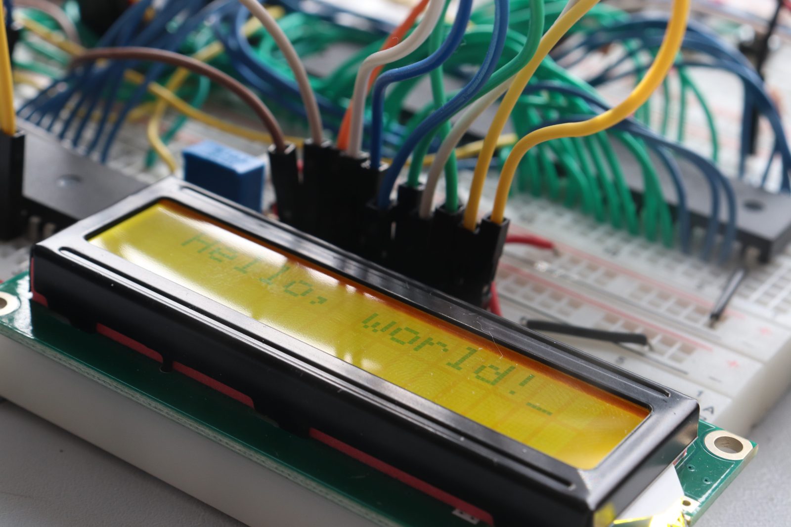
LCD Display Printing Hello World
Connected to the VIA chip, which sends control signals from the CPU to display characters.
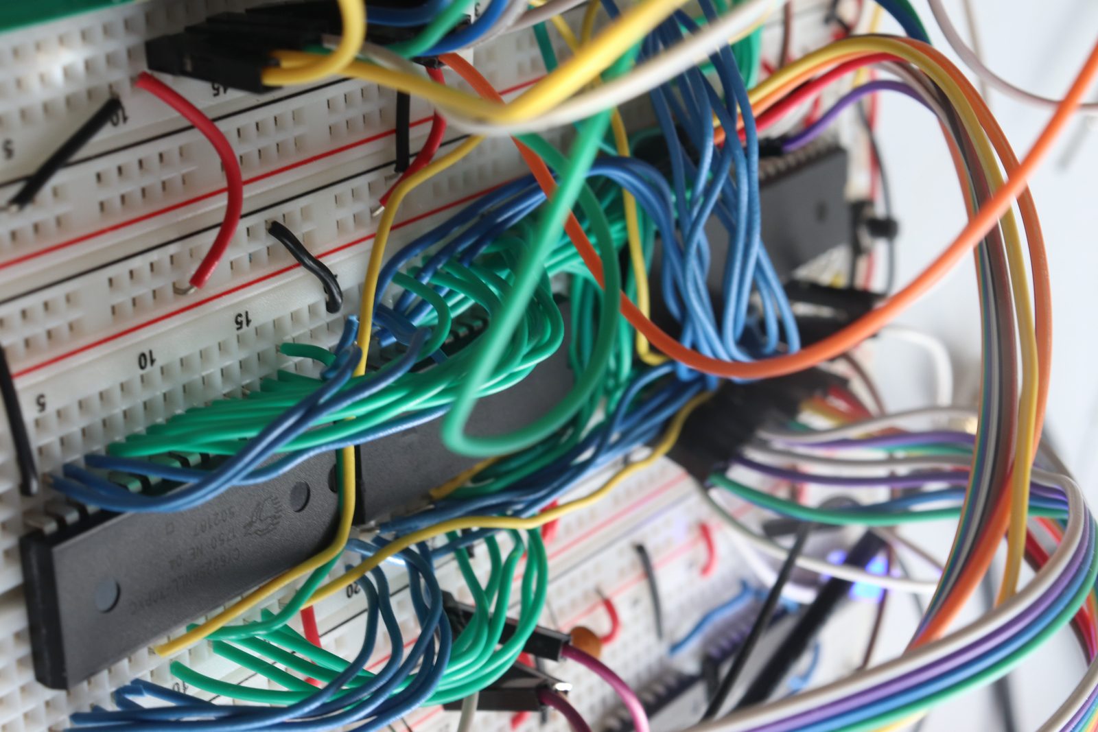
A Lot of Wires
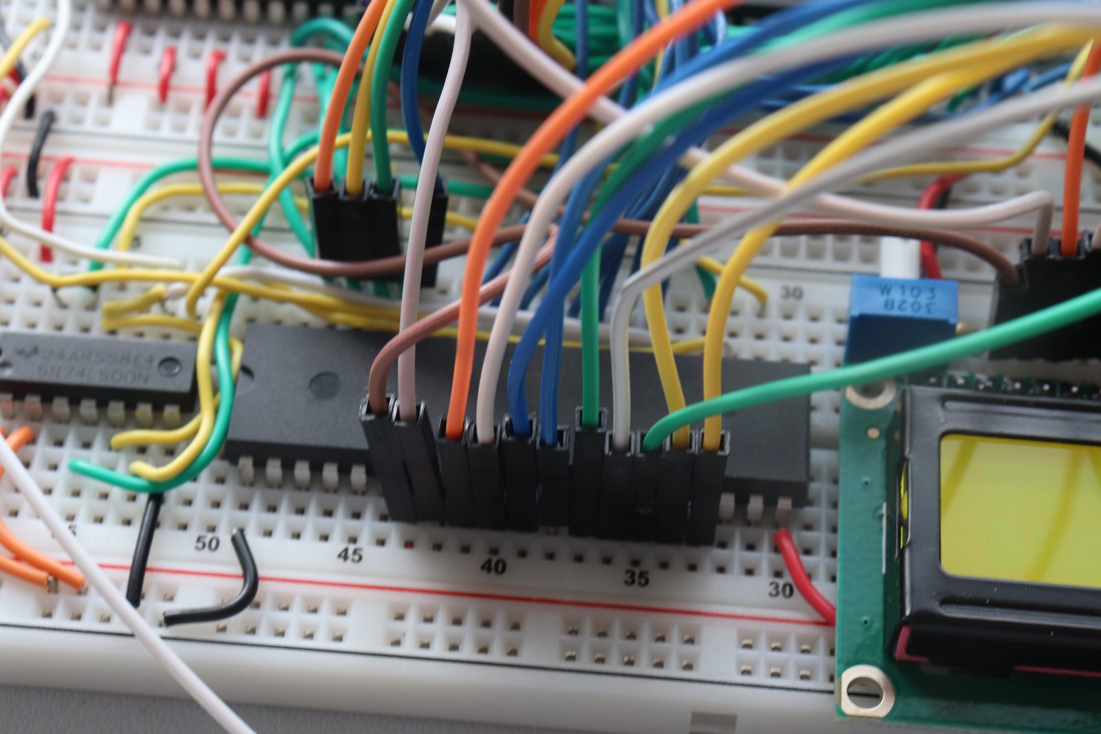
The VIA Chip (Versatile Interface Adapter)
Lets the CPU communicate with peripherals like buttons, LEDs, and displays.
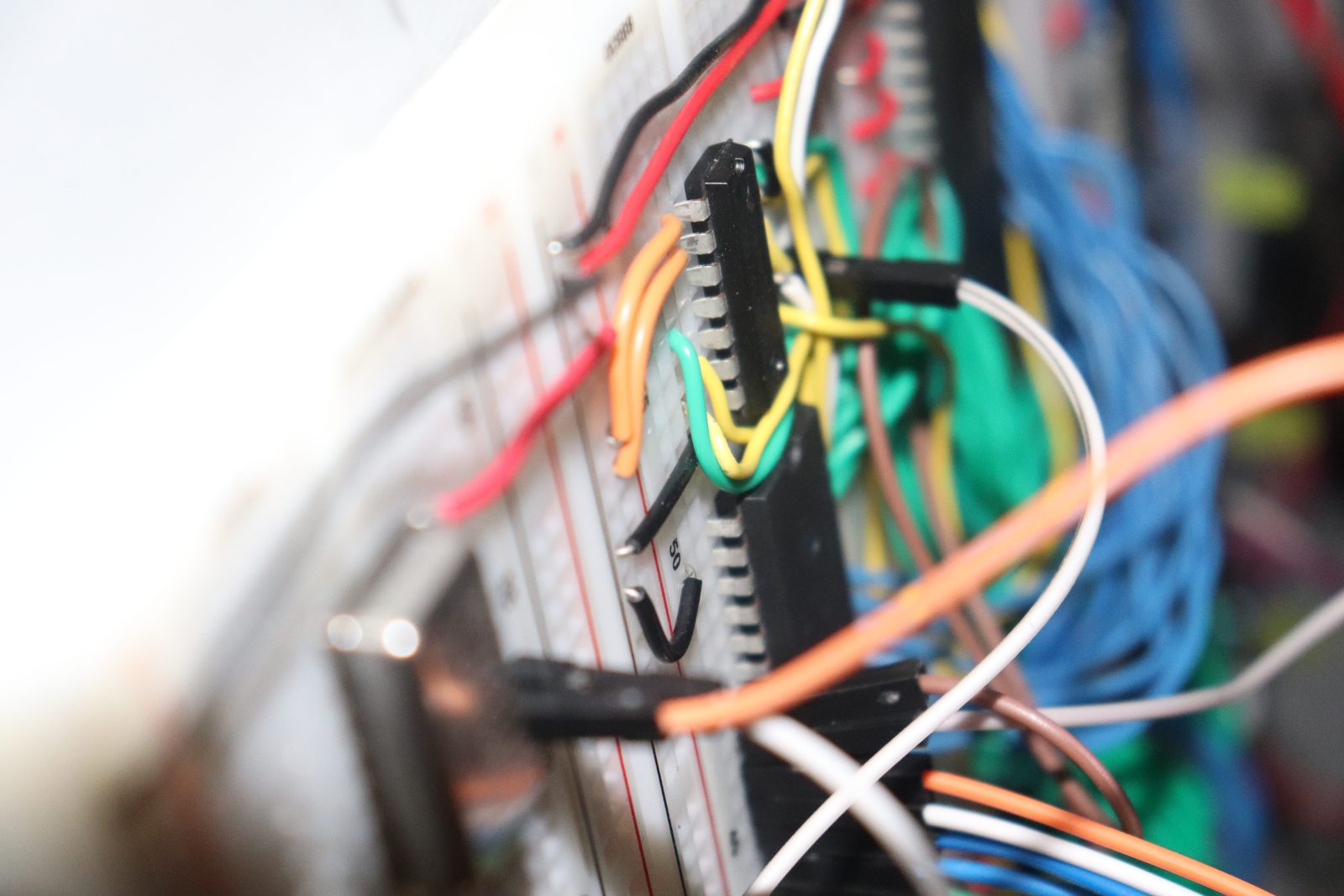
The NAND Gate
A fundamental logic gate used as a building block for more complex operations inside the computer.
Clock module
The clock module is a fundamental part of any computer. It acts as the system's heartbeat — providing the timing signals that coordinate all operations. Every signal has to be synchronized with the clock so that data is read and written at the right moments, preventing errors and keeping operation smooth. It also lets an engineer step through the program one cycle at a time, which is essential for debugging and understanding how the computer executes instructions.
But to understand how the clock works, it helps to first grasp some basic circuit concepts — voltage, transitions, and how logic gates respond to changes over time.
Next, capacitors — a key component in creating stable clock signals. Read my post on capacitors →
Understanding resistors, and how they work with capacitors to form RC (resistor-capacitor) circuits, is just as important — these circuits create the oscillations that generate clock signals. Read my post on RC circuits →
Finally, the 555 timer IC, commonly used to generate clock signals. Read my post on the 555 timer → Once you have a solid foundation in these concepts, you can appreciate how the clock generates a stable signal that synchronizes the CPU and other components.
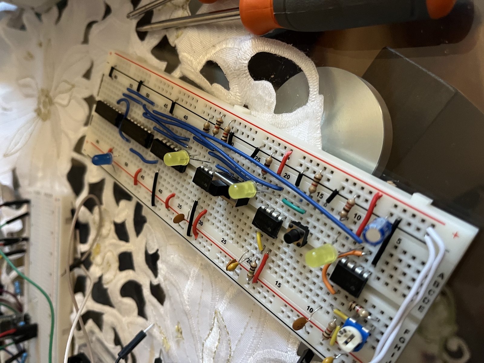
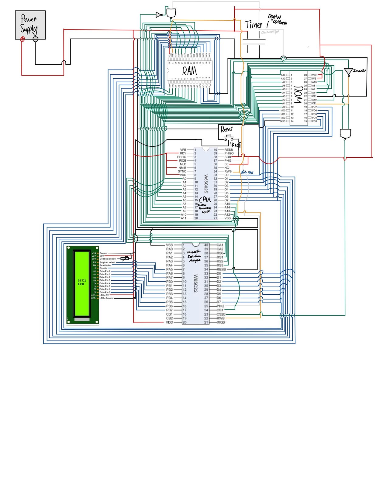
Computer architecture components
What is a computer?
A computer is a machine that takes input, processes it using a set of instructions (software), stores and retrieves data (memory), and produces output. At its core, it's a combination of logic, timing, and structured data manipulation.
The 6502 computer demonstrates these fundamental principles in their purest form, showing how binary logic gates can be combined to create complex computational systems.
What's a microprocessor (CPU)?
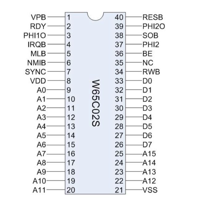
The microprocessor — also known as the Central Processing Unit (CPU) — is the brain of the computer. It reads instructions from memory and executes them, controlling all operations. A CPU consists of an arithmetic logic unit (ALU) for calculations, a control unit for instruction sequencing, and registers for temporary data storage. It has a program counter to track the current instruction (fetched from ROM — the program you write) and a stack pointer for managing subroutine calls.
Inside the microprocessor are built-in op codes (operation codes) that tell the CPU what to do, like add numbers or jump to a different instruction. The 6502 has a simple yet powerful instruction set that allows for efficient assembly programming (seen at the bottom of the page).
In this project, I used the 65C02, a classic 8-bit CPU that can process 8 bits of data at a time.
What's ROM (Read-Only Memory)?
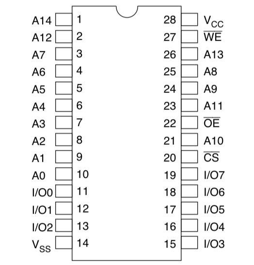
ROM stores permanent instructions that the CPU runs when powered on — like boot code or core programs. Unlike RAM, ROM retains data even when the power is off.
I programmed the ROM with custom 6502 assembly code using an EEPROM programmer. At first I used the EEPROM software to manually write the op codes in hex — this became very tedious, and writing assembly code that could then be converted into machine code turned out to be a much more efficient approach. The process was to write the assembly on a text file, assemble it, and then program the ROM by uploading the binary file to the EEPROM software and clicking program. This chip contains the bootloader and main program instructions that tell the CPU how to initialize the system and communicate with peripherals.
What's RAM (Random Access Memory)?
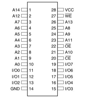
RAM is temporary memory used to store data the CPU is actively working with. It's fast and flexible, but erased when power is cut.
In my build, RAM holds variables, buffers, and subroutine data during execution. The 6502 uses a 16-bit address bus, allowing it to access up to 64KB of combined ROM and RAM memory space — though the memory map is divided into sections, with parts reserved for specific purposes like the stack and I/O devices.
What is a stack?
The stack is a special area of memory used for managing subroutines and storing return addresses. It works in a Last-In-First-Out (LIFO) way and is key to things like function calls.
In the 6502, the stack lives in memory page 1 ($0100–$01FF), and the stack pointer register tracks the current position. When you call a subroutine, the return address is automatically pushed onto the stack.
Without the stack, managing function calls and returns would be chaotic — it allows for structured programming and makes nested calls and interrupts much easier to handle. Before I had RAM installed, I couldn’t use subroutines at all, which made the code very long and hard to read. The stack allows for cleaner code and better-organized program flow.
What's a Versatile Interface Adapter (VIA)?
The VIA chip provides general-purpose input/output (GPIO) ports and timers — it's how the CPU communicates with peripherals like buttons, LEDs, and displays.
I used the 65C22 VIA to interface with the LCD display and control LEDs. It has two 8-bit I/O ports (Port A and Port B) and two programmable timers, making it incredibly versatile for hardware interfacing. Without it, I’d have to manage all I/O operations directly through the CPU — much more complex and time-consuming.
What's an LCD display?
The LCD (Liquid Crystal Display) in this project receives instructions from the CPU to display characters. I connected it through the VIA and used assembly code to send control and data signals.
The HD44780-compatible LCD controller requires specific timing sequences for initialization and character display. By sending the right combination of enable signals and data bits, I got output like "Hello World" and real-time status information.
Assembly language programming
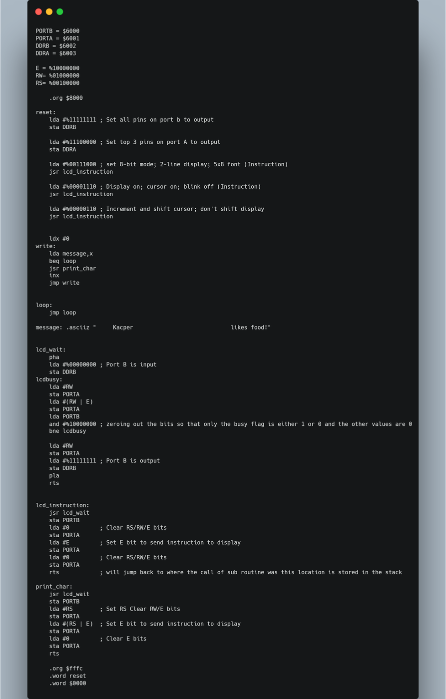
This is where it comes together. 6502 assembly is a low-level language that lets you write instructions directly for the CPU — a set of opcodes that tell it what to do, like moving data, performing arithmetic, or jumping to a different part of the program.
The 6502 has a simple yet powerful instruction set that allows for efficient programming. Each instruction corresponds to a specific operation, and you combine them to build complex programs. The assembly code is written in a text file, then assembled into machine code the CPU can execute.
In this project, I wrote a "Hello World" program that initializes the LCD display and prints the message.